Theta Lock Gripper
A high-load robotic gripper enabling reliable engagement to built solar bays under extreme alignment uncertainty and dynamic loading. Multi-state compliant mechanism designed to handle >60 kN forces and wind-induced dynamics.
The Problem
The robotic system needed to engage with built solar bays—large structural assemblies with significant variability in position due to assembly tolerances, site-to-site alignment differences, and tube-to-tube variation. Once engaged, the gripper had to maintain positive constraint through wind loads up to 60 mph while the system performed precision operations.
The core challenge was resolving conflicting requirements across operational states: loose compliance for initial alignment, controlled compliance during operation, and rigid constraint during high-load stow conditions. Traditional approaches would require separate mechanisms for each state—adding complexity, weight, and failure modes.
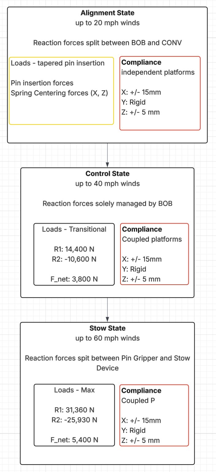
Operational States
The design resolves the conflicting requirements through staged mechanical compliance, hard-stops, and constraint switching. The system transitions through three distinct states, each with different compliance characteristics and load-carrying capacity.
Mechanism Architecture
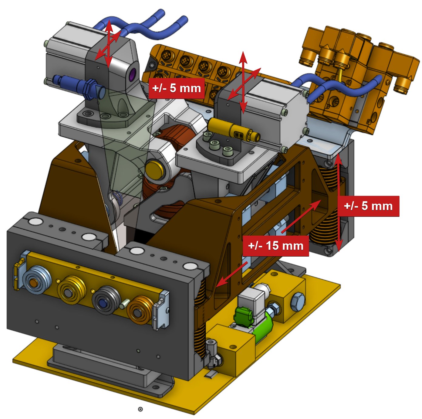
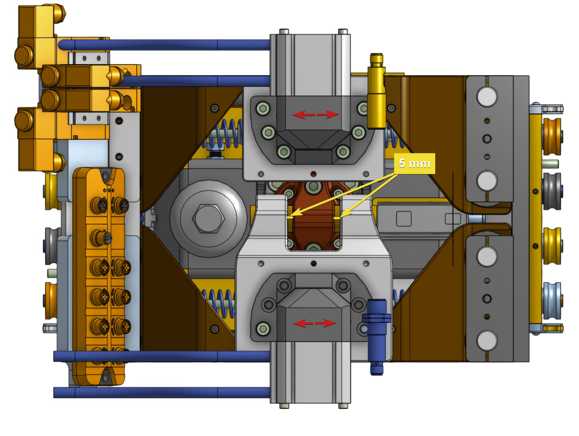
Two opposing platforms—independent or coupled depending on the Z-lock state—allow the machine to coarsely align using X, 3×Y, and 1×Z stages while remaining agnostic to assembly allowances, site alignment variation, and tube-to-tube differences.
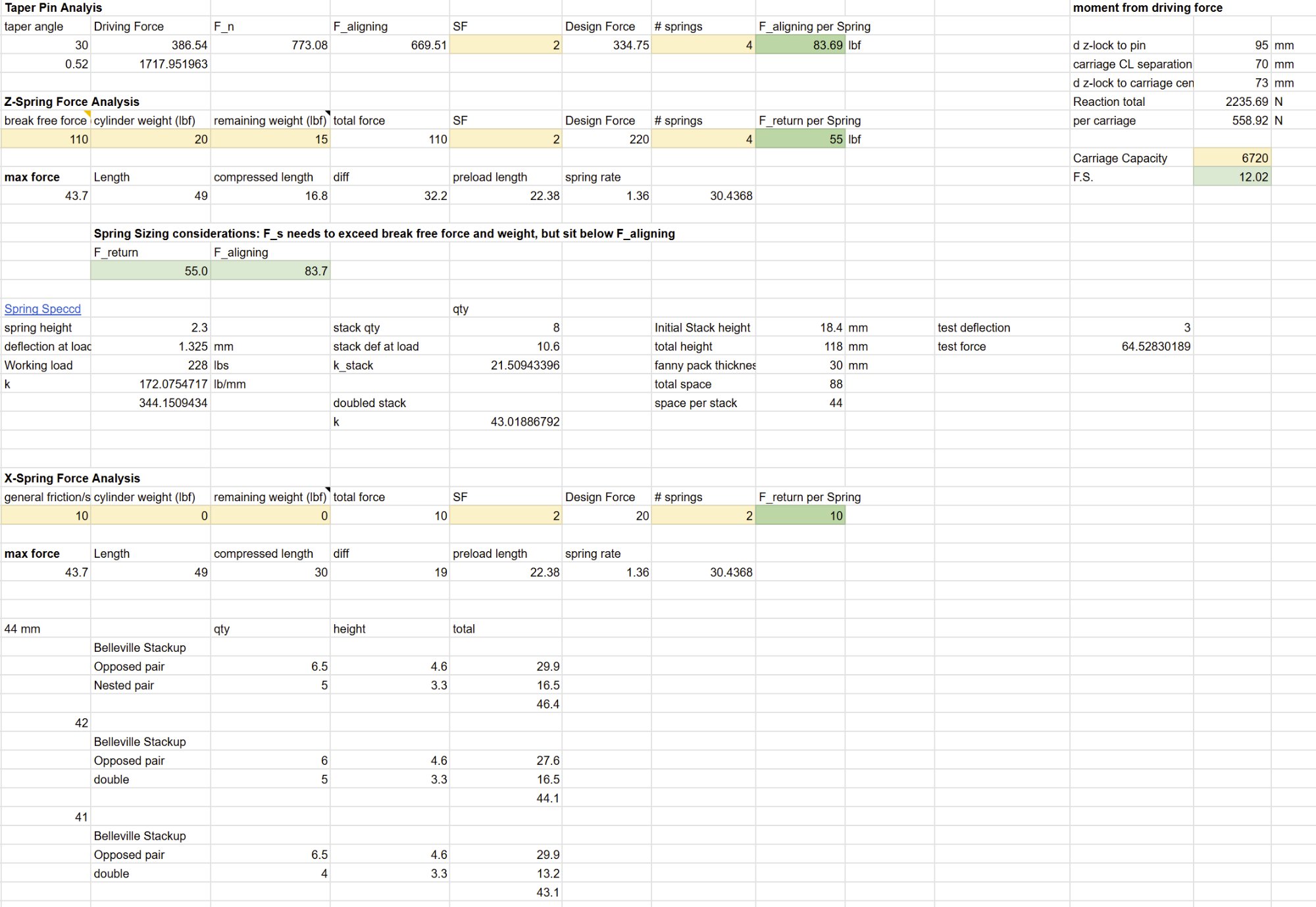
Once roughly aligned with holes in the torque tube of the solar bay, hardened tapered centering pins are driven by pneumatic cylinders, imparting centering forces on the floating platforms. The 30° taper angle was selected to balance insertion force against centering stiffness, with spring stacks sized to exceed break-free forces while staying below the aligning force threshold.
- ±5mm X/Z misalignment tolerance for passive pin insertion
- ±15mm controlled compliance to accommodate structural deflection under load
- Rigid constraint in critical axes to manage >60 kN forces
- Belleville spring stacks for high force density in compact envelope
- Integrated pneumatic actuation for state transitions
Spring & Force Analysis
The compliance stacks and structural load paths were co-designed to decouple alignment from strength. Spring sizing was driven by the constraint that spring force must exceed break-free force and weight while staying below the aligning force to allow passive centering.
Results
The system was delivered from ideation to field installation in 4 months, meeting all load requirements while maintaining the alignment flexibility needed for real-world site conditions. The decoupled compliance architecture proved robust to the variability encountered across multiple installation sites.