Next-Gen End Effector
Architecture consulting engagement defining a next-generation vacuum gripper for mobile delivery robots. Comprehensive analysis spanning pump selection, zone control, extension mechanisms, and hands-on validation testing.
The Problem
The client needed architecture definition for a next-generation vacuum gripper capable of handling diverse parcel types—from 10 lb polybags to 50 lb cardboard boxes—with high reliability under dynamic acceleration loads during last-mile delivery operations.
The system faced tight constraints: battery-powered operation on mobile robots, package surface variability affecting seal quality, and the need for a compact retractable mechanism. The central research question was whether cups positioned along deflection contours (short edge vs. long edge) would provide sufficient grasp stability under acceleration.
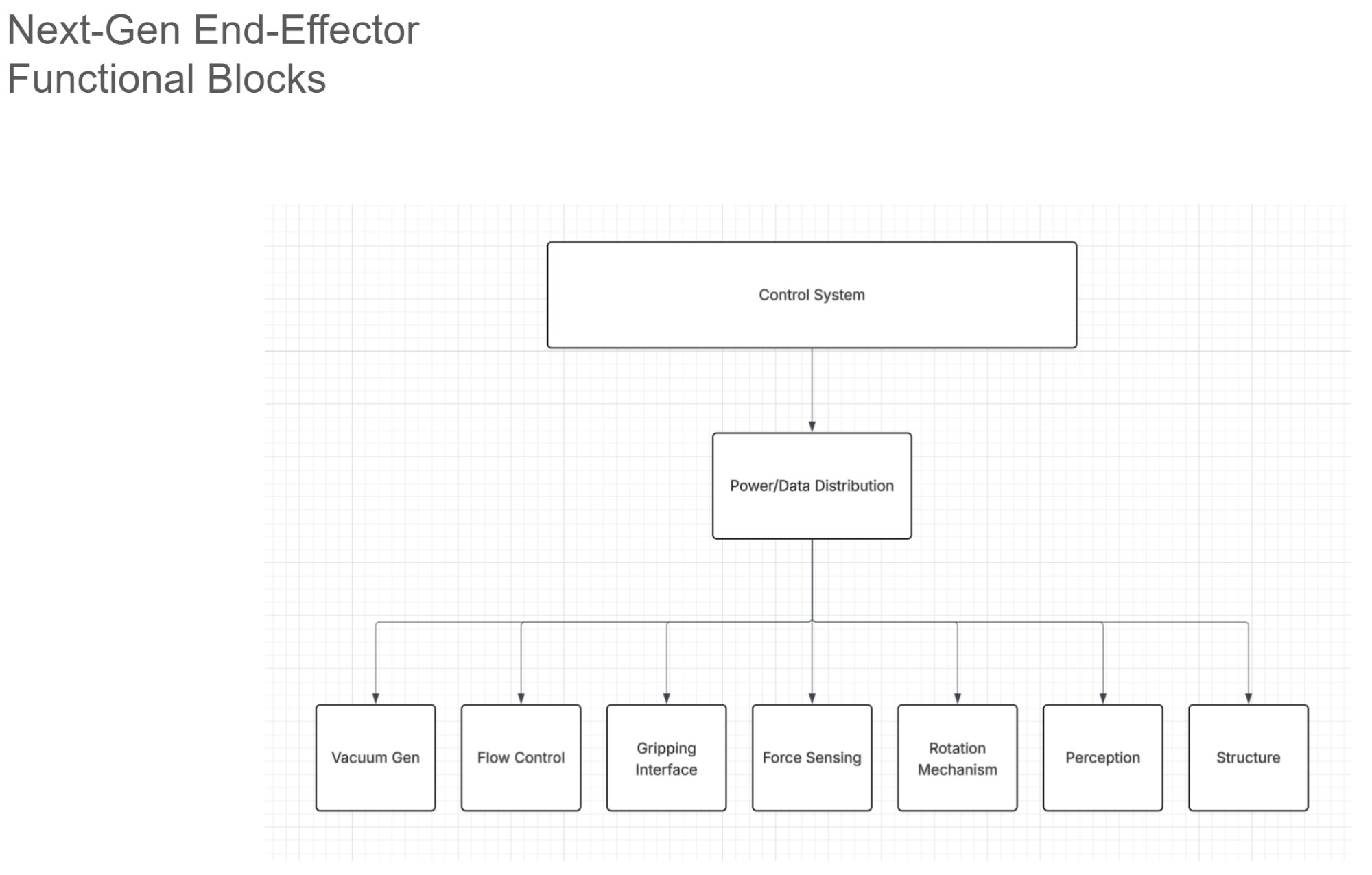
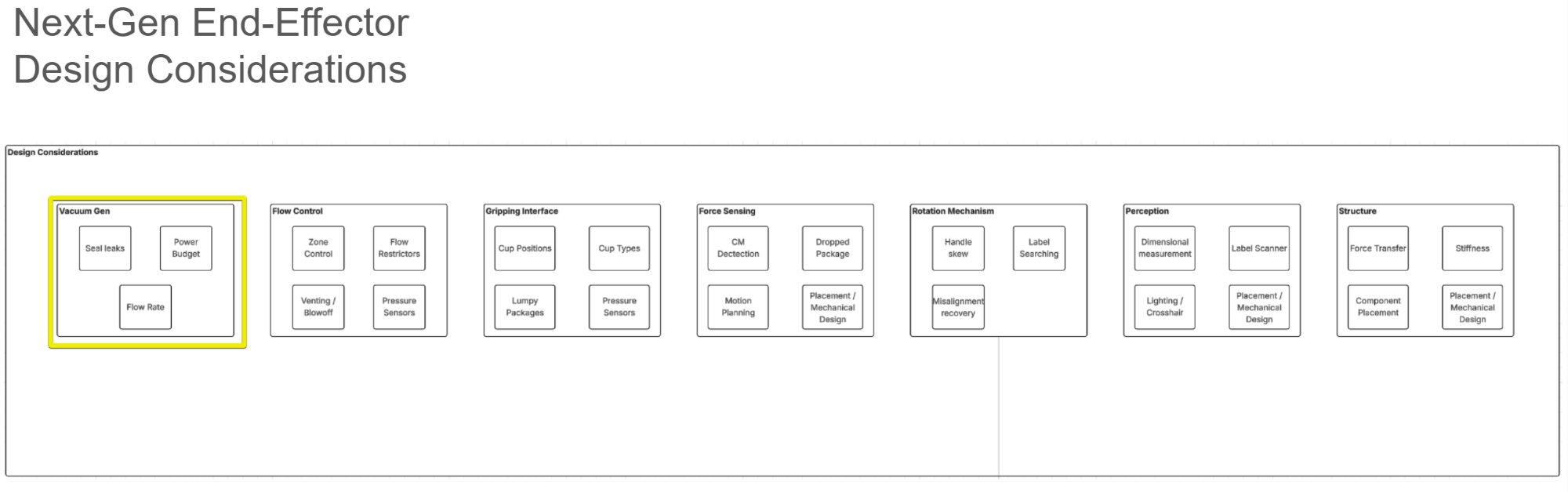
Functional Decomposition
The first deliverable was a comprehensive functional block diagram decomposing the end effector into discrete subsystems with defined interfaces. This provided a shared vocabulary and structured the subsequent trade studies.
Pump Selection & Sizing
Vacuum generation dominated the power budget and drove key system decisions. I conducted a comprehensive market survey of pump technologies—rotary vane (Becker VT series), dry claw (Busch MINK), and piston/diaphragm (Thomas 668)—evaluating flow rate, power density, noise, and DC availability for battery operation.
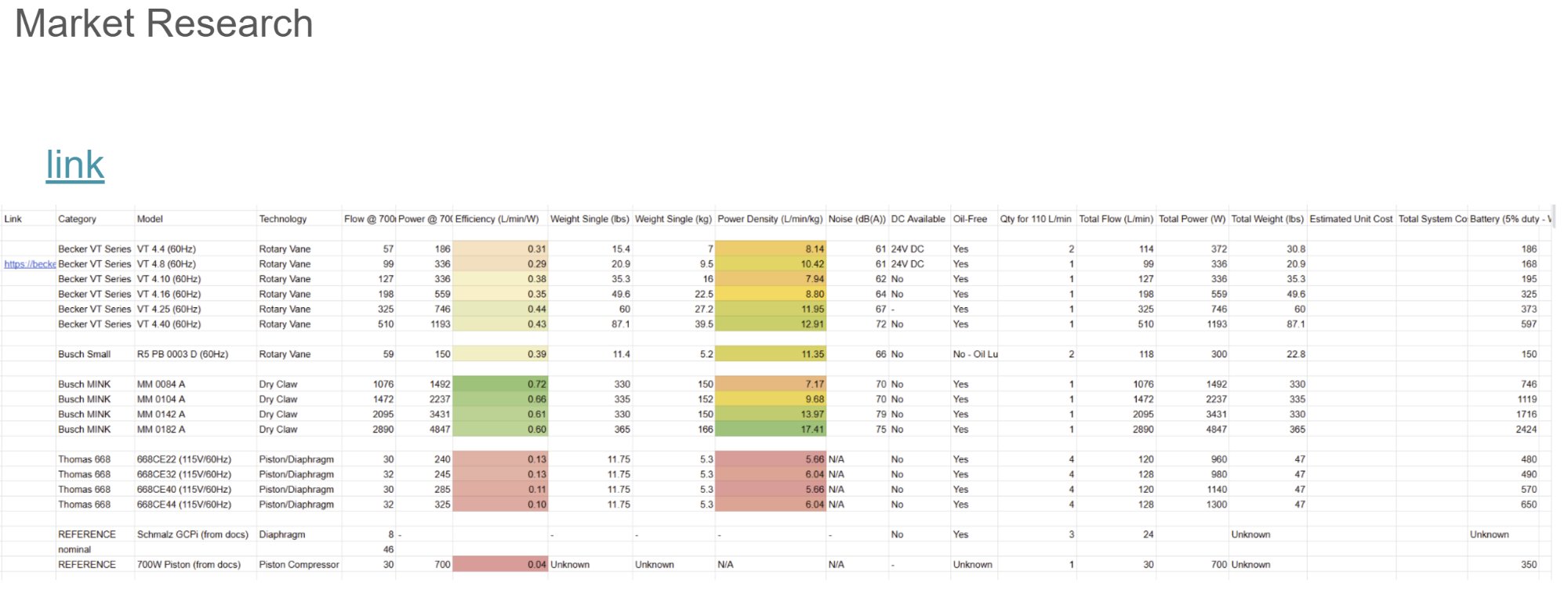
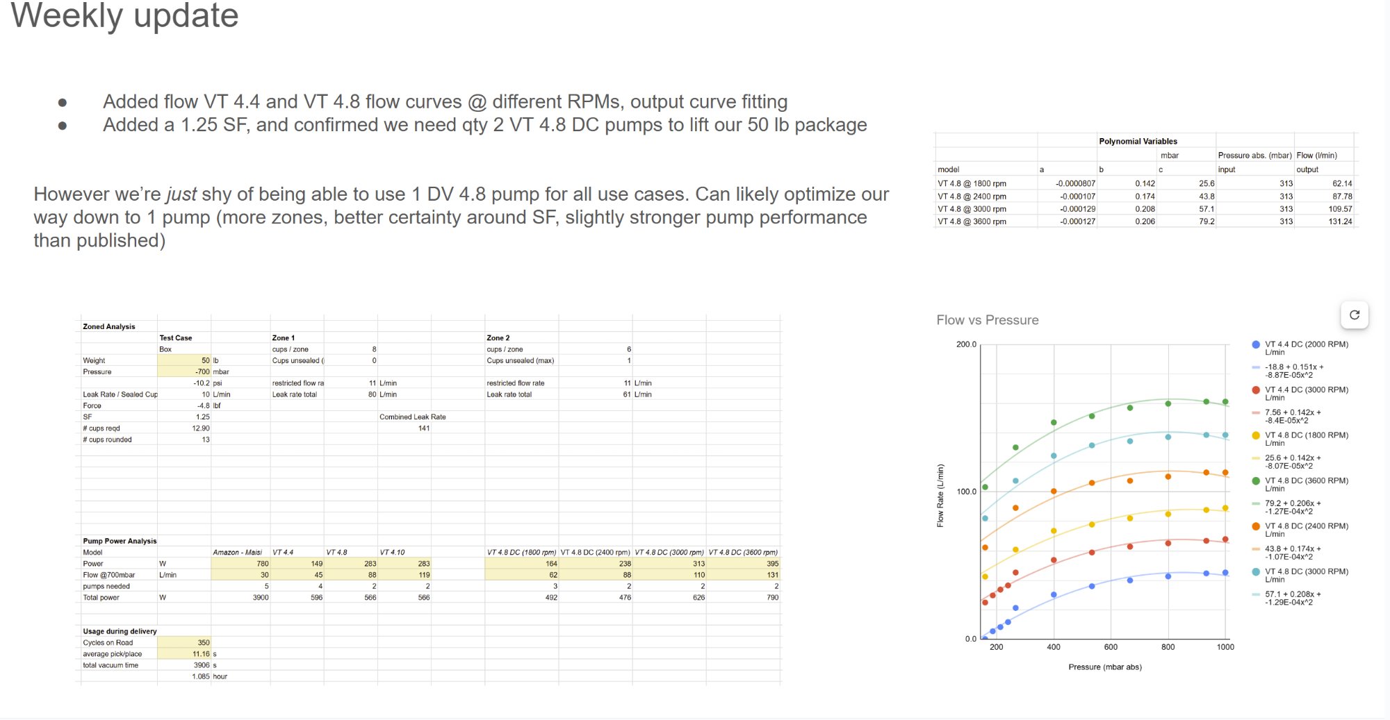
VT 4.4 and VT 4.8 have 24V DC variants that can run on 230 AC standard. The VT 4.10 exceeds flow for all test cases, but (qty 3) VT 4.4 allows flexibility with cycling pumps in/out of use for power optimization.
Flow Architecture
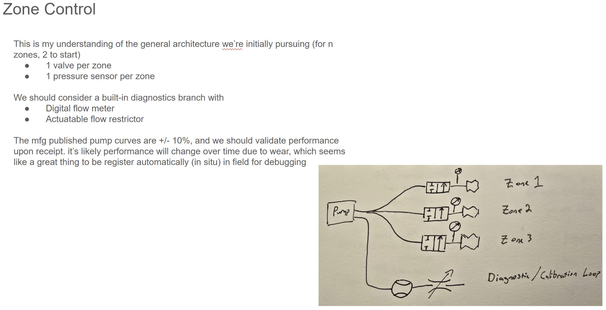
Zoned vacuum control was essential for handling packages of varying sizes efficiently. The architecture started with 2 zones, each with independent valve and pressure sensor, plus a diagnostics branch for in-situ calibration and field debugging.
- 1 valve per zone for independent control
- 1 pressure sensor per zone for feedback
- Diagnostics branch with digital flow meter and actuatable flow restrictor
- 16mm main tubing run, reducing to 10mm at cups
- Manifold: ½" NPT inlet to 10× ⅜" NPT outlets
Pressure Drop & Pump Sizing
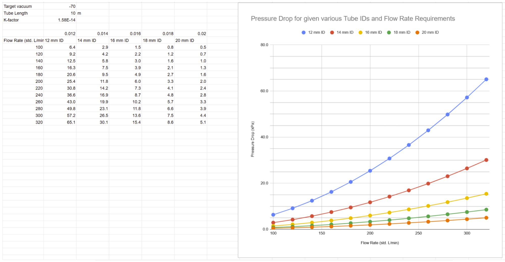
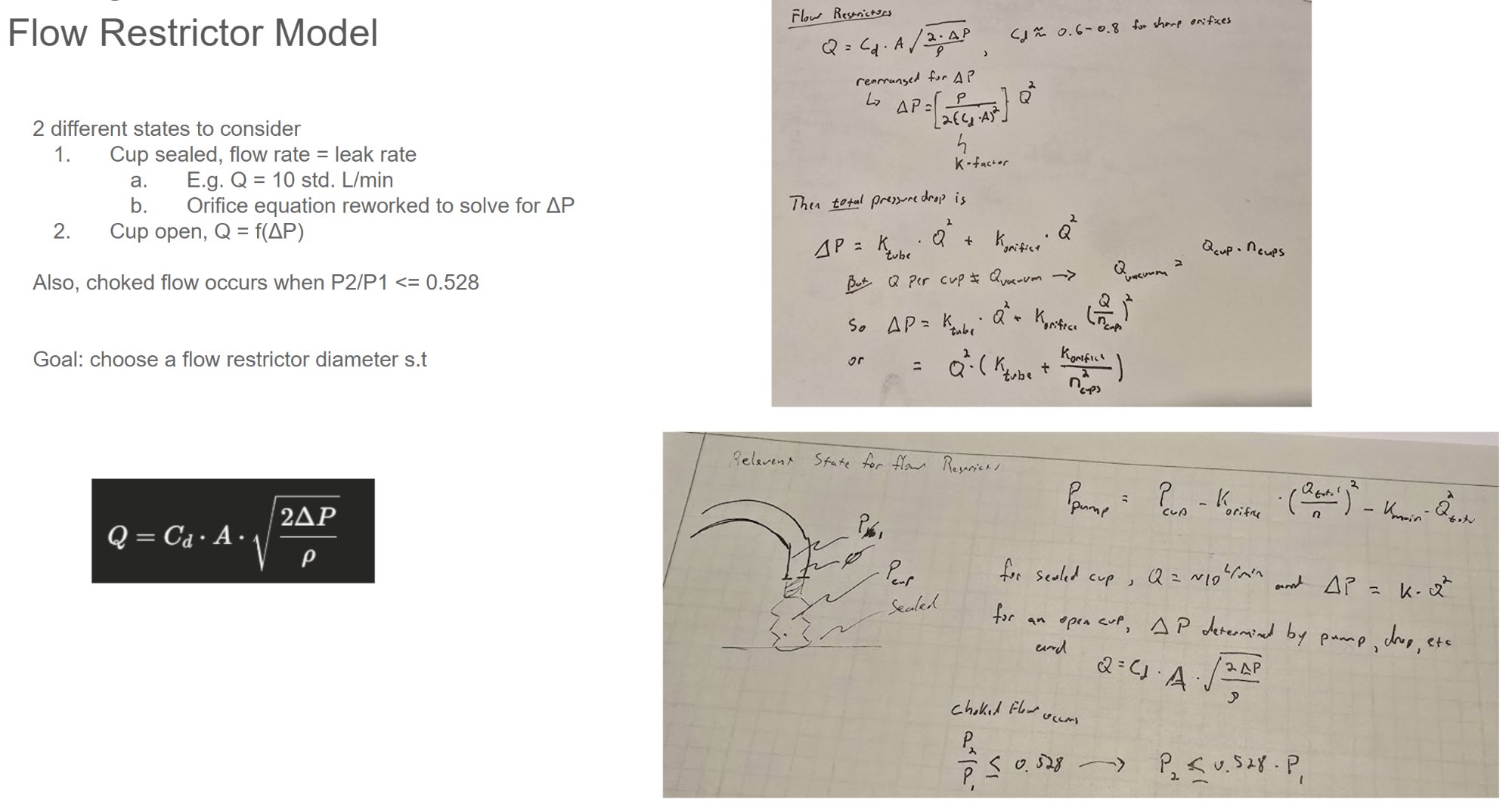
Developed a comprehensive flow model to understand how tubing diameter, flow rate, and target vacuum interact to drive pump count. The model combines tube pressure drop (K-factor relationship) with orifice flow equations for restrictors, accounting for both sealed cups (leak rate) and open cups (orifice-limited flow).
The analysis revealed that tube ID has dramatic impact on system sizing—12mm tubing shows ~65 kPa drop at 320 L/min while 20mm drops only ~5 kPa. This directly translates to pump count: at -70 kPa target with 200 L/min flow, 12mm tubing requires 4+ pumps while 18mm needs only 2.
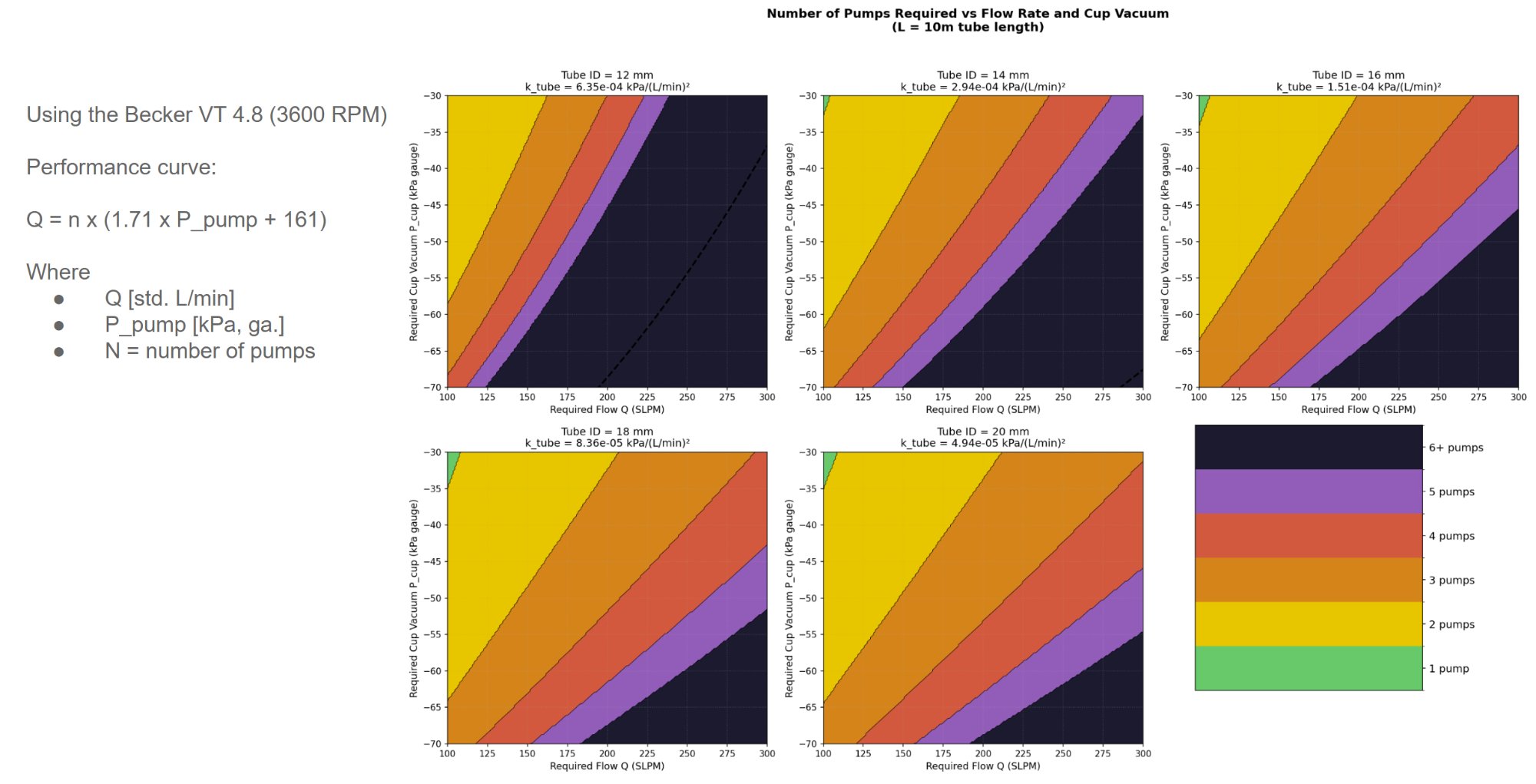
Two states to consider: (1) cup sealed where flow rate = leak rate (~10 L/min), and (2) cup open where Q = f(ΔP) via orifice equation. Choked flow occurs when P2/P1 ≤ 0.528. Goal: choose restrictor diameter such that total pressure drop ΔP = K_tube·Q² + K_orifice·(Q/n_cups)² stays within pump capacity.
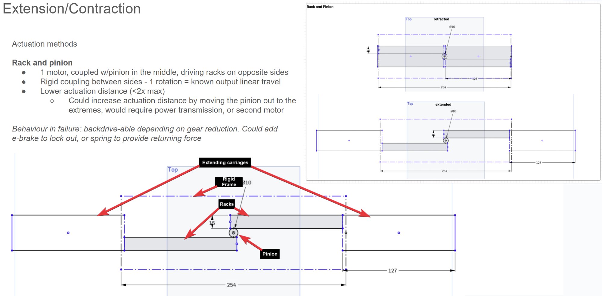
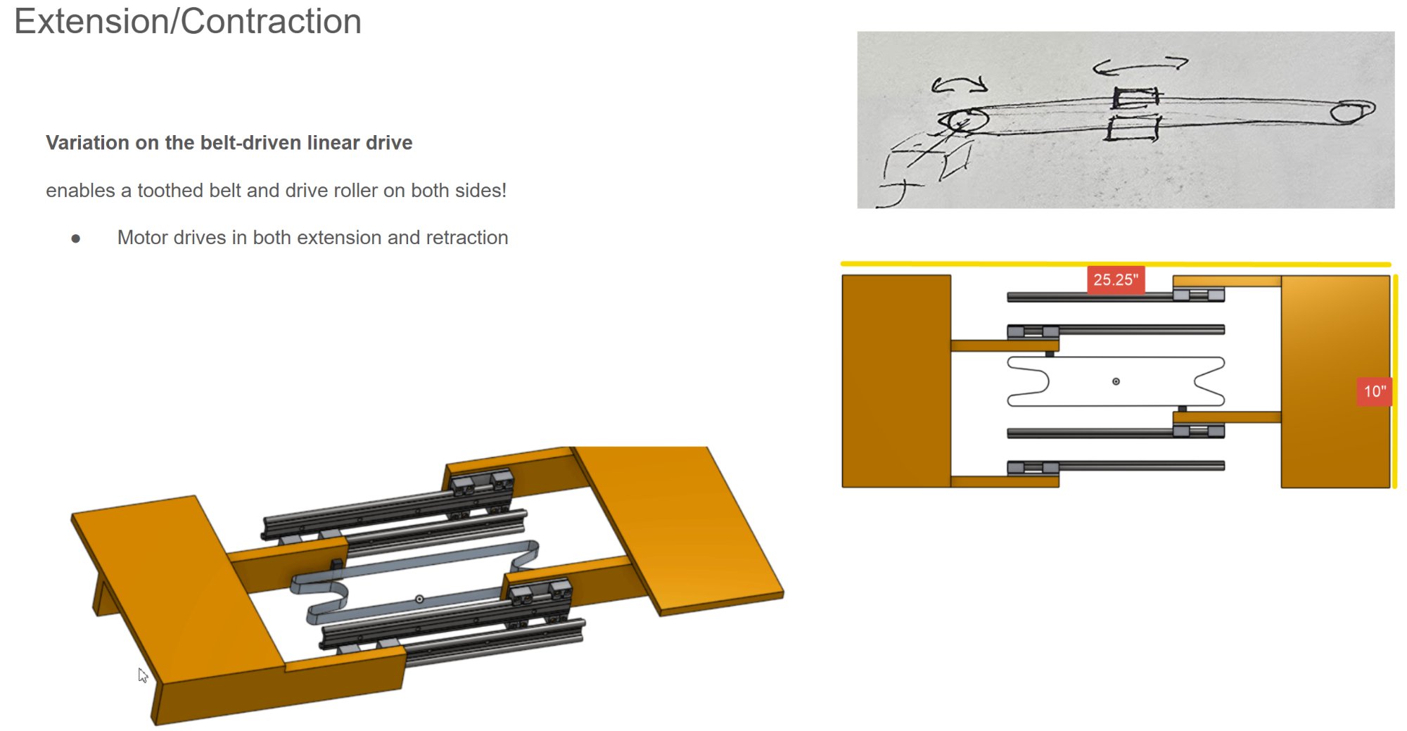
Actuation Trade Study
The gripper required a retraction mechanism to stow compactly on the robot while extending to reach packages. I evaluated three primary actuation approaches against reach ratio, failure behavior, and coupling rigidity.
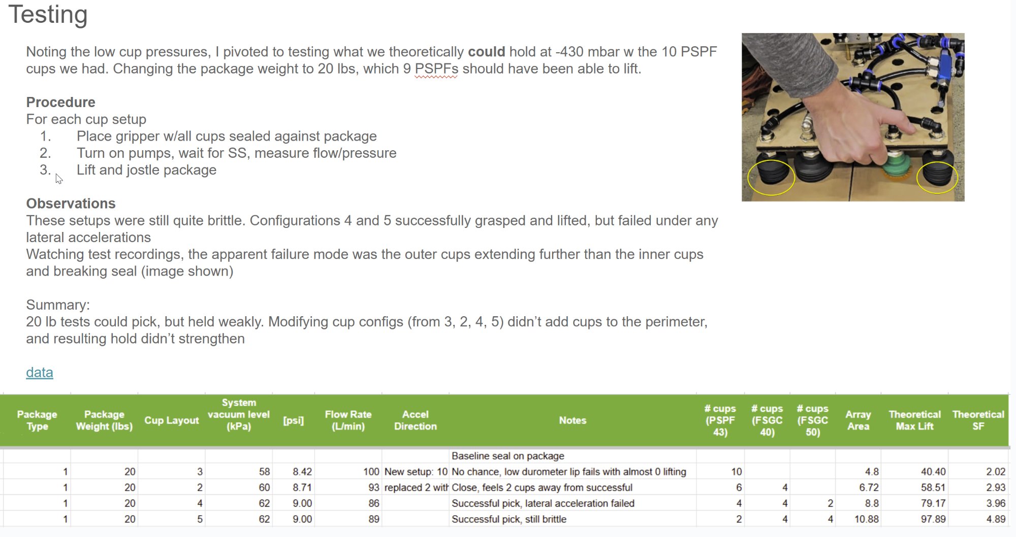
Hands-On Experimentation
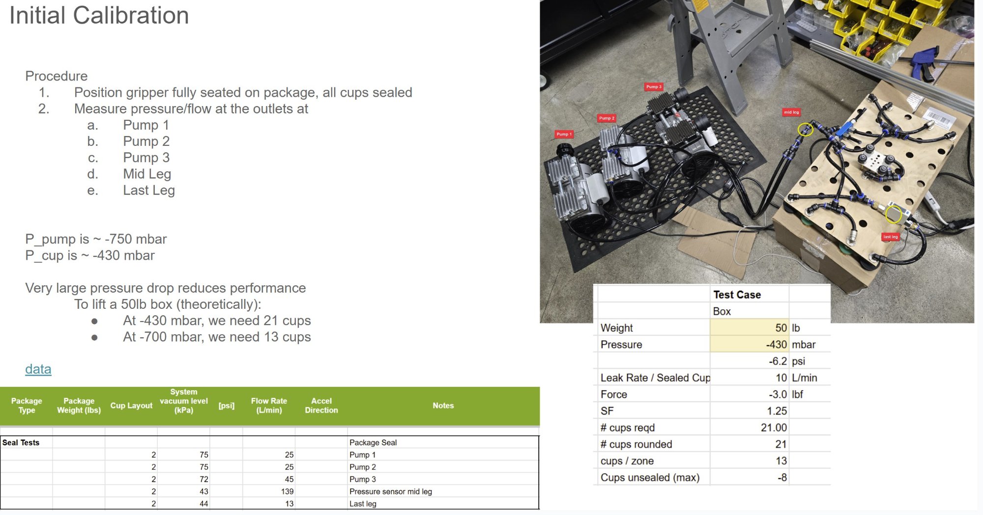
Initial calibration revealed significant pressure drop in the test setup: pump pressure of ~-750 mbar yielded only ~-430 mbar at the cups—a 41% loss during seal tests and 17-23% during subsequent tests. This meant theoretical lift of 13 cups at -700 mbar required 21 cups at -430 mbar.
Testing at 20 lb revealed that grasps were quite brittle. Configurations successfully grasped and lifted but failed under lateral acceleration. The apparent failure mode was outer cups extending further than inner cups and breaking seal.
Theoretical cups required ≠ cups needed on gripper. Package deformation hugely impacts pick success—cups in the middle have reduced, if not negligible, impact on pick success under this failure mode.
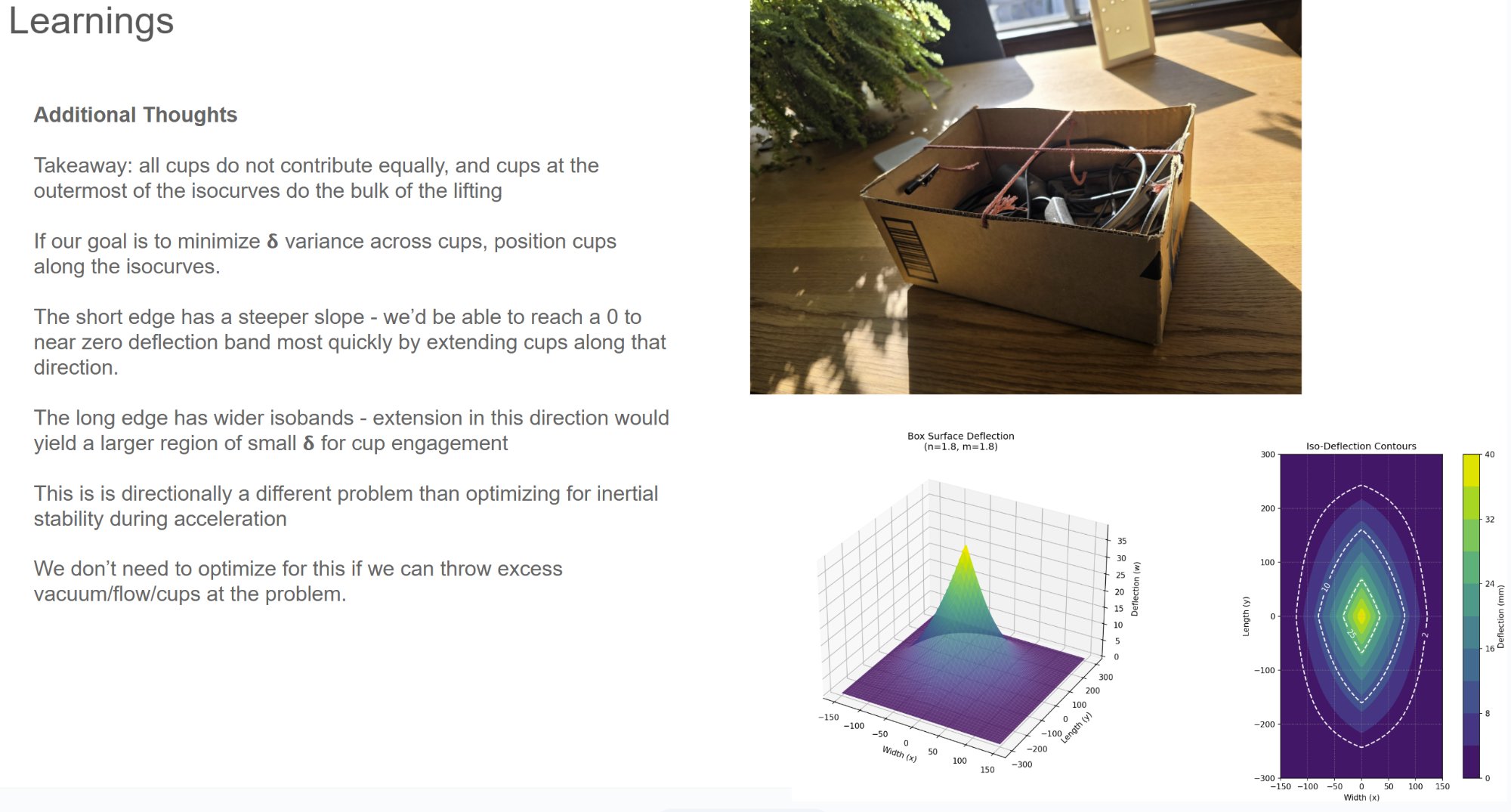
Deflection Analysis
Developed a surface deflection model to understand cup contribution. When lifted at center, cardboard box flaps become tension elements with maximum δ_z coupled between long and short edges. Cups at the outermost isocurves do the bulk of the lifting.
The short edge has steeper slope—reaching near-zero deflection band most quickly by extending cups along that direction. The long edge has wider isobands yielding a larger region of small δ for cup engagement. This is directionally different from optimizing for inertial stability during acceleration.